
Wired Remote Signal Test - Y1 / Y2 / Y3
This procedure checks the remote controller supply voltage and communication signal integrity on systems using Y1, Y2 and Y3 terminals.
Quick Answer
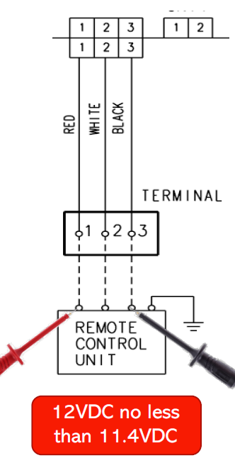
- Y1 to Y3: approximately 12 V DC
- Minimum acceptable Y1-Y3 voltage: 11.4 V DC
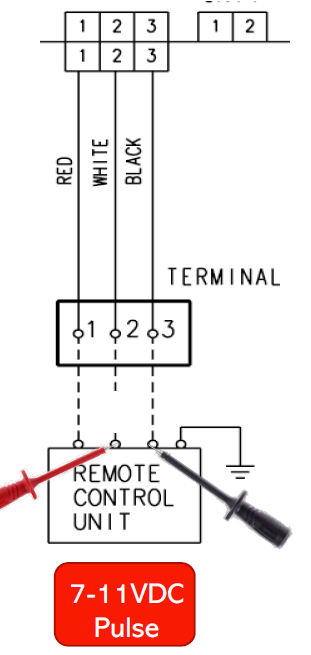
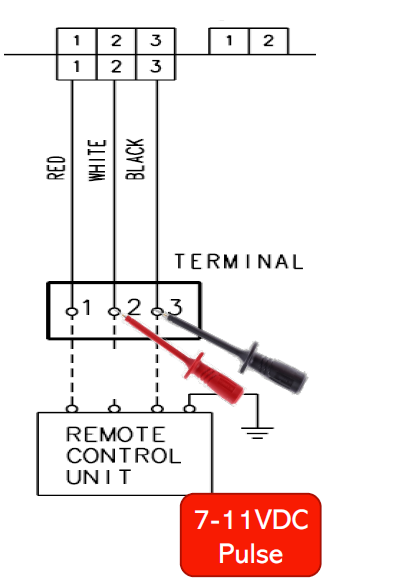
- Communication pulse signal: approximately 7-12 V DC pulsing
What This Test Checks
The test confirms:
- Remote controller DC supply is present.
- The Y1-Y3 supply voltage is within the acceptable range.
- A communication pulse is present on the Y2 circuit.
- The wiring between the remote controller and indoor unit is intact.
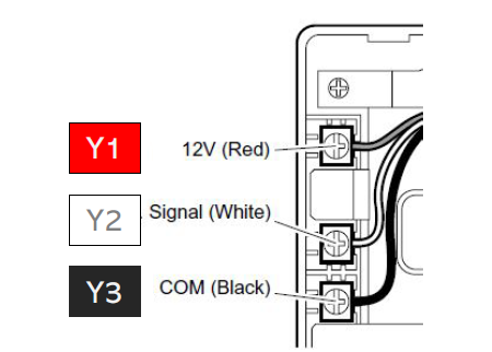
Tools Required
- Digital multimeter set to DC voltage
Test Procedure
- Measure voltage between Y1 and Y3.
- Confirm the reading is approximately 12 V DC and not below 11.4 V DC.
- Disconnect the Y2 conductor.
- Measure between Y3 and the disconnected Y2 cable going toward the indoor unit.
- Measure between Y3 and the Y2 terminal.
- Check for a pulsing DC signal in the approximate range of 7-12 V DC.
Pass Criteria
| Test | Pass Criteria |
|---|---|
| Y1-Y3 supply voltage | ≥ 11.4 V DC, nominally around 12 V DC |
| Y2 communication signal | Pulsing signal approximately 7-12 V DC |
If the Test Fails
Y1-Y3 below 11.4 V DC or 0 V
Check wiring continuity and connections. If the wiring is correct, investigate the controller PCB / supply circuit.
Check wiring continuity and connections. If the wiring is correct, investigate the controller PCB / supply circuit.
No pulse signal present
Repair the wiring between the remote controller and indoor unit, then repeat the applicable System Signal Test - Indoor to Outdoor.
Repair the wiring between the remote controller and indoor unit, then repeat the applicable System Signal Test - Indoor to Outdoor.
Technician Checklist
- Confirm the system uses Y1/Y2/Y3 wired remote terminals.
- Set the multimeter to DC voltage.
- Confirm Y1-Y3 is at least 11.4 V DC.
- Disconnect Y2 as shown in the procedure.
- Check both sides of the Y2 circuit relative to Y3.
- Confirm a 7-12 V DC pulse is present.
- If voltage is low or absent, check wiring and supply PCB.
- If the pulse is absent, repair the communication wiring and retest.