Overview
When using General Airstage VRF systems equipped with 8-port or 12-port Refrigerant Branch Boxes (RB units), certain installation conditions require port merging — where two or more RB outlets are combined to serve a single indoor circuit.
Proper configuration of the S300 DIP switch (“Concurrent Output”) on the RB PCB is essential to ensure the correct communication and control of merged branches.
Incorrect DIP switch configuration may result in branch communication errors, incorrect EEV operation, or RB board fault codes.
1. DIP Switch S300 – “Concurrent Output” Settings
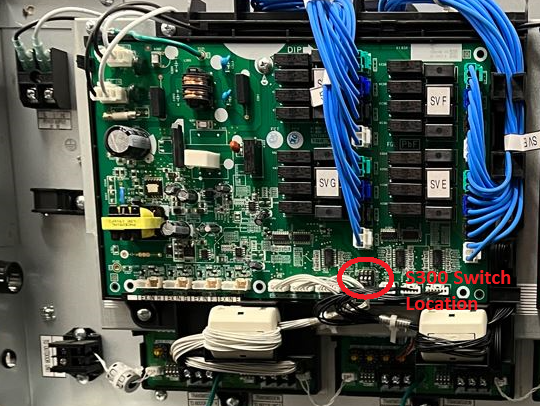
The S300 DIP switch is located on the main control PCB within the RB unit.
These settings define which ports are merged and which terminal block corresponds to the combined output.
A. Merging Two Ports
(Example: Combining Branch A & B, or E & F)
| PCB Board Section | Branches Merged | S300 DIP Switch Settings | Cable Terminal Connection |
|---|---|---|---|
| For Branches A–D | A & B | ① OFF / ② OFF / ③ ON | For branch B |
| C & D | ① ON / ② OFF / ③ OFF | For branch D | |
| For Branches E–H | E & F | ① OFF / ② ON / ③ OFF | For branch F |
| G & H | ① OFF / ② OFF / ③ ON | For branch H | |
| For Branches I–L | I & J | ① ON / ② OFF / ③ OFF | For branch J |
| K & L | ① OFF / ② ON / ③ ON | For branch L |
⚙️ Note:
When merging two ports, always connect refrigerant piping and signal cables to the lower branch terminal of the pair (B, D, F, H, J, or L).
Do not merge non-sequential ports (e.g., B + C or D + E).
B. Merging Four Ports
(Example: Combining Branches A–D, E–H, or I–L)
| PCB Board Section | Branches Merged | S300 DIP Switch Settings | Cable Terminal Connection |
|---|---|---|---|
| For Branches A–D | A, B, C, D | ① ON / ② ON / ③ ON | For branch D |
| For Branches E–H | E, F, G, H | ① ON / ② ON / ③ ON | For branch H |
| For Branches I–L | I, J, K, L | ① ON / ② ON / ③ ON | For branch L |
⚙️ Note:
When merging four ports, refrigerant lines and signal cables must all terminate on the last port of the group (D, H, or L).
Ensure refrigerant piping lengths and flow balance are within General's design parameters for merged branch operation.
2. Important Wiring and Installation Notes
Each RB PCB manages four branch outputs; DIP switch addressing allows multiple boards to coordinate refrigerant and communication distribution.
Always power off the system before changing DIP switch settings.
Confirm U1/U2 transmission wiring polarity is consistent between the outdoor unit, RB unit, and indoor units.
After configuration, re-initialize system communication to register merged ports (using [F3:00] “Forced Cooling Test Run” if required).
Label the merged branches clearly for future service identification.
3. Common Field Errors and Solutions
| Symptom | Possible Cause | Resolution |
|---|---|---|
| One indoor not cooling in a merged pair | DIP switch S300 incorrectly set | Recheck DIP settings (refer table) |
| RB error LED flashing | Mismatched communication or incorrect terminal connection | Verify U1/U2 connections and DIP orientation |
| System reports “Indoor Shortage” error | DIP setting not matching branch piping layout | Correct DIP and reinitialize system |
| No operation from merged group | Communication board fault or wiring reversal | Check continuity, polarity, and board function |
When Merging more then one port together on a 8 or a 12 port refrigerant branch box the following switches need to be set on S300.
The S300 switch location is located below.