
General Assist Technical Reference
Low Noise and Peak Cut - External Input and Output
Applicable outdoor units: AOTG30-54LATL
External contact control for noise reduction, demand limitation and status outputs.
The outdoor control PCB provides two external inputs and two external outputs. Low Noise Mode and Peak Cut Mode are activated by closing a field-supplied contact. Error and compressor status can be passed to a building management or monitoring device.
Electrical work: Installation and PCB setting changes must be completed by a suitably qualified technician. Isolate power before connecting or disconnecting plugs, and discharge static electricity before touching the outdoor PCB.
1. Connector allocation
| Function | Connector | Signal type |
|---|---|---|
| Low Noise Mode | CN10 | External input - closed contact activates the function. |
| Peak Cut Mode | CN11 | External input - closed contact activates the function. |
| Error Status | CN12 | External output - active when a malfunction occurs. |
| Compressor Status | CN13 | External output - active while the compressor is running. |
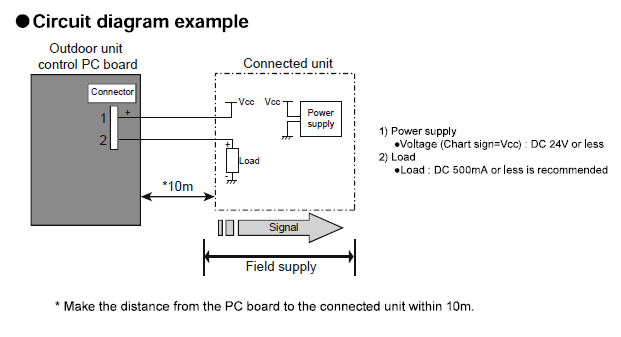
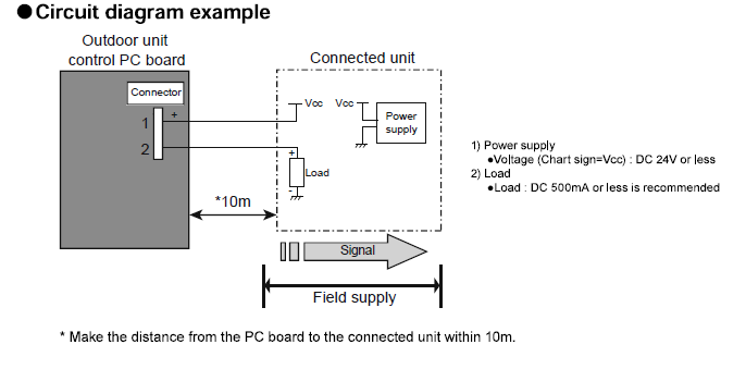
External Connect Kit: UTY-XWZXZ3 is required for each external input or output connection. Keep the cable distance from the outdoor PCB to the connected device within 10 m.
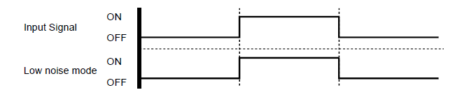
2. Low Noise Mode - CN10
Low Noise Mode reduces the normal operating sound of the outdoor unit. Capacity may reduce depending on outdoor temperature and system load.
| Input | Operation |
|---|---|
| Contact closed / ON | Low Noise Mode active. |
| Contact open / OFF | Normal operation. |
3. Peak Cut Mode - CN11
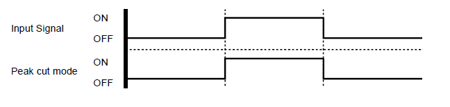
Peak Cut Mode suppresses the outdoor unit input current to a selected percentage of rated input. This can support demand-management or site power-limitation requirements.
| Input | Operation |
|---|---|
| Contact closed / ON | Peak Cut Mode active at the percentage selected on the PCB. |
| Contact open / OFF | Normal operation. |
Important: The selectable values are percentages of rated input. A setting of 100% allows rated input, while 50% or 75% limits input to that proportion. A 0% setting prevents normal compressor input while the Peak Cut signal is active.
4. External outputs - CN12 and CN13
| Output | Active condition | Electrical limit |
|---|---|---|
| CN12 - Error Status | Output turns ON when a system malfunction occurs. | External supply: DC 24 V or less. Recommended load: DC 500 mA or less. |
| CN13 - Compressor Status | Output turns ON while the compressor is operating. | External supply: DC 24 V or less. Recommended load: DC 500 mA or less. |
5. Outdoor PCB setting procedure
Before changing settings: Stop the air conditioner. The outdoor PCB buttons are SW1 MODE, SW2 SELECT, SW3 ENTER, SW4 EXIT and SW5 PUMP DOWN.
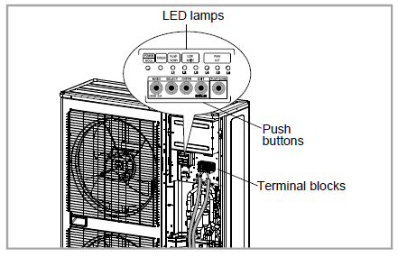
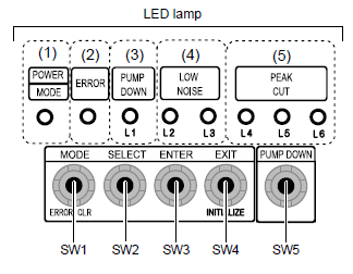
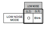
Set the Low Noise level
- Press and hold MODE (SW1) for at least 3 seconds to enter Local Setting Mode.
- Confirm the POWER/MODE LED blinks 9 times, then press ENTER (SW3).
- Press SELECT (SW2) until the Low Noise Mode selection is displayed, then press ENTER (SW3).
- Use SELECT (SW2) to choose Mode 1 or Mode 2 according to the L4-L6 LED pattern shown in the manual.
- Press ENTER (SW3) to save.
- Press EXIT (SW4) to return to the normal operating status display.
Set the Peak Cut input ratio
- Press and hold MODE (SW1) for at least 3 seconds.
- Confirm the POWER/MODE LED blinks 9 times, then press ENTER (SW3).
- Press SELECT (SW2) until the Peak Cut Mode selection is displayed, then press ENTER (SW3).
- Use SELECT (SW2) to choose 0%, 50%, 75% or 100% of rated input according to the L4-L6 LED pattern.
- Press ENTER (SW3) to save.
- Press EXIT (SW4) to return to the normal operating status display.
6. Quick commissioning check
| Step | Check |
|---|---|
| 1 | Confirm the correct UTY-XWZXZ3 lead is connected to the required PCB connector. |
| 2 | Confirm contact and cable ratings, polarity where applicable, and cable length of 10 m or less. |
| 3 | Set the Low Noise level or Peak Cut percentage before testing the input. |
| 4 | Operate the external contact and confirm the relevant PCB LED indication and system response. |
| 5 | Label the field wiring and record the selected setting in the commissioning documentation. |
Assist Technical Support
Australia: 1300 364 484
New Zealand: +64 4 568 8761