How to Test Temperature Thermistors
Temperature thermistors can fail in two main ways:
Loss of resistance within the thermistor itself.
Incorrect DC voltage supply from the PCB (Printed Circuit Board).
Before testing, measure the ambient temperature so you have a reference point.
1. Testing Thermistor Resistance
To check the thermistor’s resistance:
Disconnect the thermistor from the PCB.
Set your multimeter to the resistance (Ω) setting.
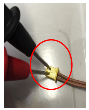
Flip the thermistor clip over to expose the small metal contact strips.
Place the multimeter probes on the metal strips.
If your multimeter probes are too large, use a thin piece of wire or a paper clip to bridge the connection
Wrap the wire around the probe tip and touch the other end to the metal strip.
If the measured resistance does not correspond to the expected value for the ambient temperature, replace the thermistor.
2. Testing PCB Voltage Supply to the Thermistor
There are two methods to check the DC voltage supply from the PCB to the thermistor:
Method 1: Measure voltage from the top side of the PCB while the thermistor is still plugged in.
Method 2: Measure voltage from the underside of the PCB with the thermistor plugged in.
When performing this test:
Always use a DC neutral reference. The black wire in the fan motor connector can be used as your DC neutral.
Each thermistor has two pins:
One pin should read approximately 5V DC.
The other pin will vary depending on the ambient temperature.
If either of these voltages is incorrect, the PCB is faulty and must be replaced.

Summary of Actions
If the thermistor resistance test fails → Replace the thermistor.
If the DC voltage test fails → Replace the PCB.

